Introduction
Lately I got four Nexus 3064PQ switches (http://www.cisco.com/c/en/us/products/collateral/switches/nexus-3000-series-switches/white_paper_c11-661242.html)
I wanted to perform some redundancy tests.
So I just wanted to find out what happens if vPC peer-keepalive link is down or vPC peer link is down or one or more switches are reloaded.
Here is our setup:
- Switch0 – Nexus 3K (software ver. 6.0(2)U2(2))
- Switch1 – Nexus 3K (software ver. 5.0(3)U3(2a))
- Switch2 – Nexus 3K (software ver. 5.0(3)U3(2a))
- Switch3 – Nexus 3K (software ver. 5.0(3)U3(2a))
- Switch4 – Catalyst 2960S
- Switch5 – Catalyst 2960S
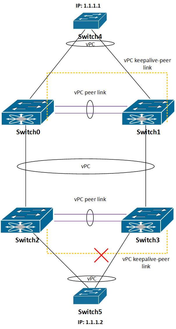
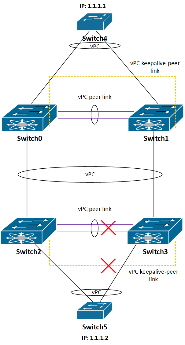
And the picture below show the setup:
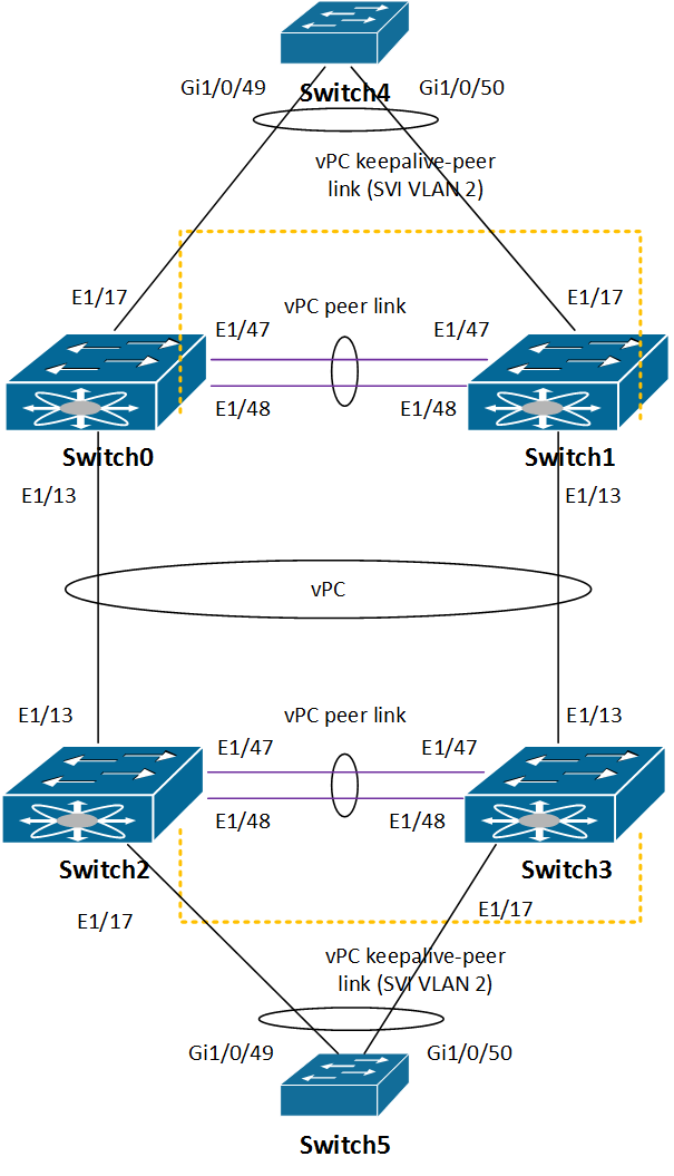
In this setup switches 4 and 5 are only used to test connectivity between them, each has its SVI (Switch4: 1.1.1.1 and Switch5: 1.1.12). To test redundancy I was pinging Switch5 from Switch4 and vice versa.
Configuration
Before we go to configuration, I’ve always been wondering if two vPC peer devices have to have the same NX-OS version running in order to form vPC adjacency.
Switch0 is running on NX-OS version 6.0(2)U2(2) and Switch1 on 5.0(3)U3(2a):
Switch0# sh ver | i system
system: version 6.0(2)U2(2)
Switch1# sh ver | i system
system: version 5.0(3)U3(2a)
Switch2 and 3 run on 5.0(3)U3(2a). It happens that vPC adjacency between Switch0 and 1 is established, but if I reload one of them during redundancy tests there will be connection loss. So even if sh vpc command shows that everything is OK, it is not!
vPC domain
First let’s configure vPC domain on all four switches.
Switch0# sh run vpc
vpc domain 8
role priority 10
system-priority 10
delay restore 120
peer-gateway
auto-recovery
Switch1# sh run vpc
vpc domain 8
role priority 10
system-priority 10
delay restore 120
peer-gateway
auto-recovery
Switch2# sh run vpc
vpc domain 9
role priority 10
system-priority 10
delay restore 120
peer-gateway
auto-recovery
Switch3# sh run vpc
vpc domain 9
role priority 10
system-priority 10
delay restore 120
peer-gateway
auto-recovery
vPC peer-keepalive
While configuring vPC domain on all switches, you’ve noticed that peer-keepalive command is missing. Before doing it, I was thinking how should we deal with it.
Should we use mgmt0 interface for it or some other physical interface or maybe SVI or to put normal port in routed mode (no switchport)? I did some testing using SVI for peer-keepalive communication, and there are some caveats:
– SVI should be excluded from vPC domain configuration (dual-active exclude interface-vlan), otherwise it will be suspended if something goes wrong
– If one vPC switch member stops working (reload, power outage, etc…) and comes back again, the SVI will be UP, yet peer-keepalive will be down. I’m not sure what might be the reason for that, but I had to issue shut/no shut on SVI to make it work again (version 5.0(3)U3(2a)). As it happened after I upgraded all switches to version 6.0(2)U2(2) problem disappeared.
I decided to configure E1/13 interface on each switch in non-routed mode and to use them for peer-keepalive link.
Now on each switch we’ll add peer-keepalive destination source command.
vPC domain 8
Switch0(config-vpc-domain)#peer-keepalive destination 10.0.0.2 source 10.0.0.1
Switch1(config-vpc-domain)#peer-keepalive destination 10.0.0.1 source 10.0.0.2
vPC domain 9
Switch2(config-vpc-domain)#peer-keepalive destination 10.0.1.2 source 10.0.1.1
Switch3(config-vpc-domain)#peer-keepalive destination 10.0.1.1 source 10.0.1.2
Note: if you use SVIs to bring peer-keepalive link UP, don’t forget to exclude the VLAN interface from vPC configuration, otherwise vPC might not come UP after reload.
vPC domain 8
Switch0(config-vpc-domain)#dual-active exclude interface-vlan 8
Switch1(config-vpc-domain)#dual-active exclude interface-vlan 8
vPC domain 9
Switch2(config-vpc-domain)#dual-active exclude interface-vlan 9
Switch3(config-vpc-domain)#dual-active exclude interface-vlan 9
vPC peer-link
Before vPC peers form adjacency, we’ll configure port-channel as vpc peer-link:
The configuration is same for all 4 Nexus switches (Switch0, Switch1, Switch2 and Switch3):
interface port-channel1
switchport mode trunk
spanning-tree port type network
no negotiate auto
vpc peer-link
For peer-link, we’ll use two ports on each switch:
interface Ethernet1/47
switchport mode trunk
channel-group 1 mode active
interface Ethernet1/48
switchport mode trunk
channel-group 1 mode active
vPC status
After we have configured vPC peer-keepalive and vPC peer-link let’s check the status of the vPC:
Switch0# sh vpc
Legend:
(*) – local vPC is down, forwarding via vPC peer-link
vPC domain id : 8
Peer status : peer adjacency formed ok
vPC keep-alive status : peer is alive
Configuration consistency status : success
Per-vlan consistency status : success
Type-2 consistency status : success
vPC role : primary
Number of vPCs configured : 2
Peer Gateway : Enabled
Peer gateway excluded VLANs : –
Dual-active excluded VLANs : –
Graceful Consistency Check : Enabled
Auto-recovery status : Enabled (timeout = 240 seconds)
vPC Peer-link status
———————————————————————
id Port Status Active vlans
— —- —— ————————————————–
1 Po1 up 1-2,10
vPC status
—————————————————————————-
id Port Status Consistency Reason Active vlans
—— ———– —— ———– ————————– ———–
10 Po10 up success success 10
11 Po11 up success success 10
As we can see vPC adjacency came UP. Even if Switch0 and Switch1 have different NX-OS versions running.
Note: after I tested redundancy between switches 4 and 5, it looks like that using different major NX-OS versions will not work when it comes to vPC between end hosts. So mixing different NX-OS versions is not a good idea.
Redundancy tests
After we configured each pair of N3K switches to work with vPC setup, now it’s time to perform redundancy tests:
- Reload Switch0, Switch1, Switch2, Switch3 one at a time.
- Reload Switch0, Switch2 both at the same time
- vPC keepalive link between Switch0 and Switch1 is disconnected, vPC peer link is OK
- vPC keepalive link between Switch2 and Switch3 is disconnected, vPC peer link is OK
- vPC peer link between Switch0 and Switch1 is disconnected, vPC keepalive link is OK
- vPC peer link between Switch2 and Switch3 is disconnected, vPC keepalive link is OK
- both vPC keepalive and peer link between Switch0 and Switch1 are disconnected
- both vPC keepalive and peer link between Switch2 and Switch3 are disconnected
- Shutting down uplinks on Switch4 and Switch5
1. Reload Switch0, Switch1, Switch2, Switch3 one at a time
In this test we’ll reload each switch at a time, one by one and we’ll wait that the reloaded switch becomes fully operational before we move to the next one.
The test was successful, no connection loss between switches 4 and 5.
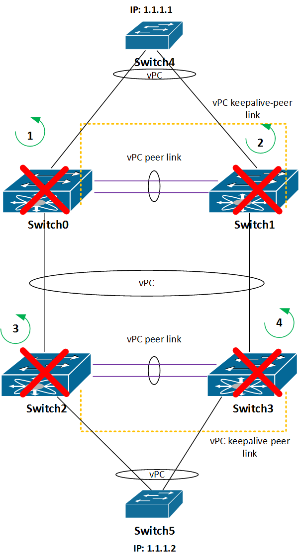
2. Reload Switch0, Switch3 both at the same time
In this test we’ll reload one switch at the same time in each vPC pair, which means Switch0 and Switch3.
This test was also successful, with no connection loss between switches 4 and 5. Switches 1 and 2 have taken over the forwarding, as expected.
3. vPC keepalive link between Switch0 and Switch1 is disconnected, vPC peer link is OK
Now let’s see what happens if the peer keepalive link is down.
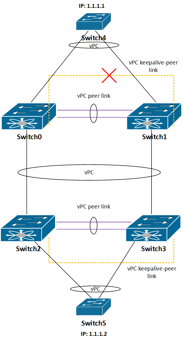
Is the connectivity between switches 4 and 5 still there? Yes, it is, as peer keepalive link is there just to resolve “split brain” situations, when the peer link goes down. Of course, it is highly recommended to fix peer keepalive link to avoid even worse situations.
4. vPC keepalive link between Switch2 and Switch3 is disconnected, vPC peer link is OK
The same behavior as in step 3.
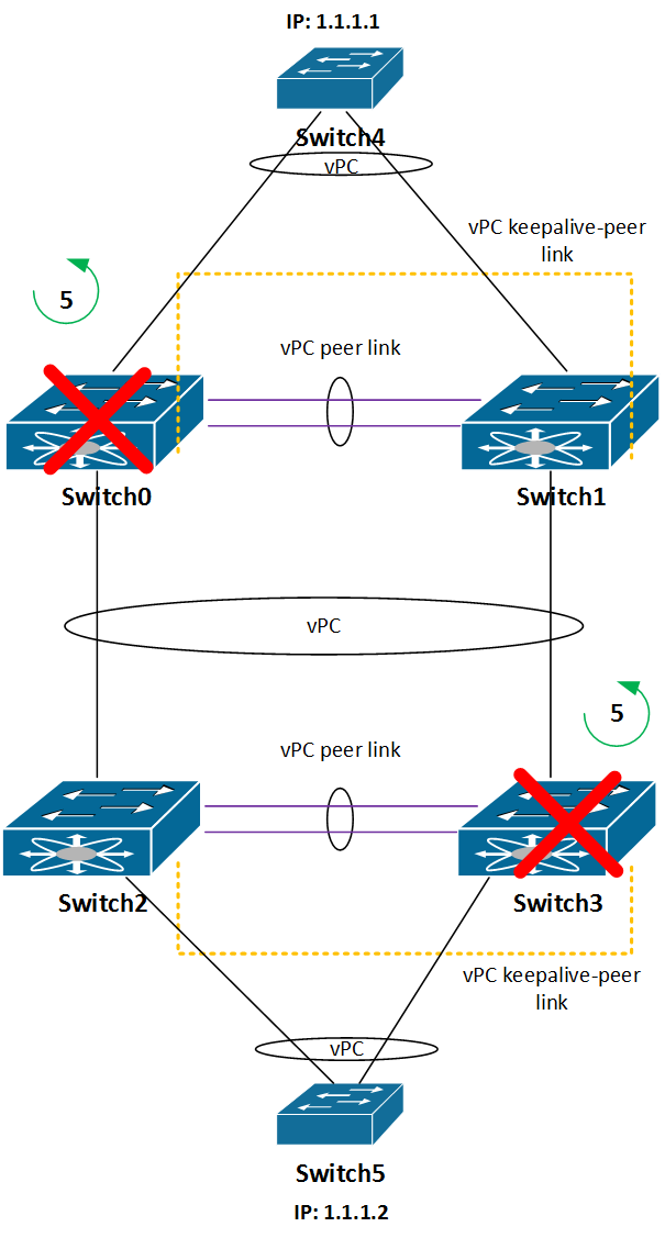
5. vPC peer link between Switch0 and Switch1 is disconnected, vPC keepalive link is OK
Now it becomes interesting. When I have shut down the peer link between switches 0 and 1, Switch 1 suspended its vPC ports. See the picture below:
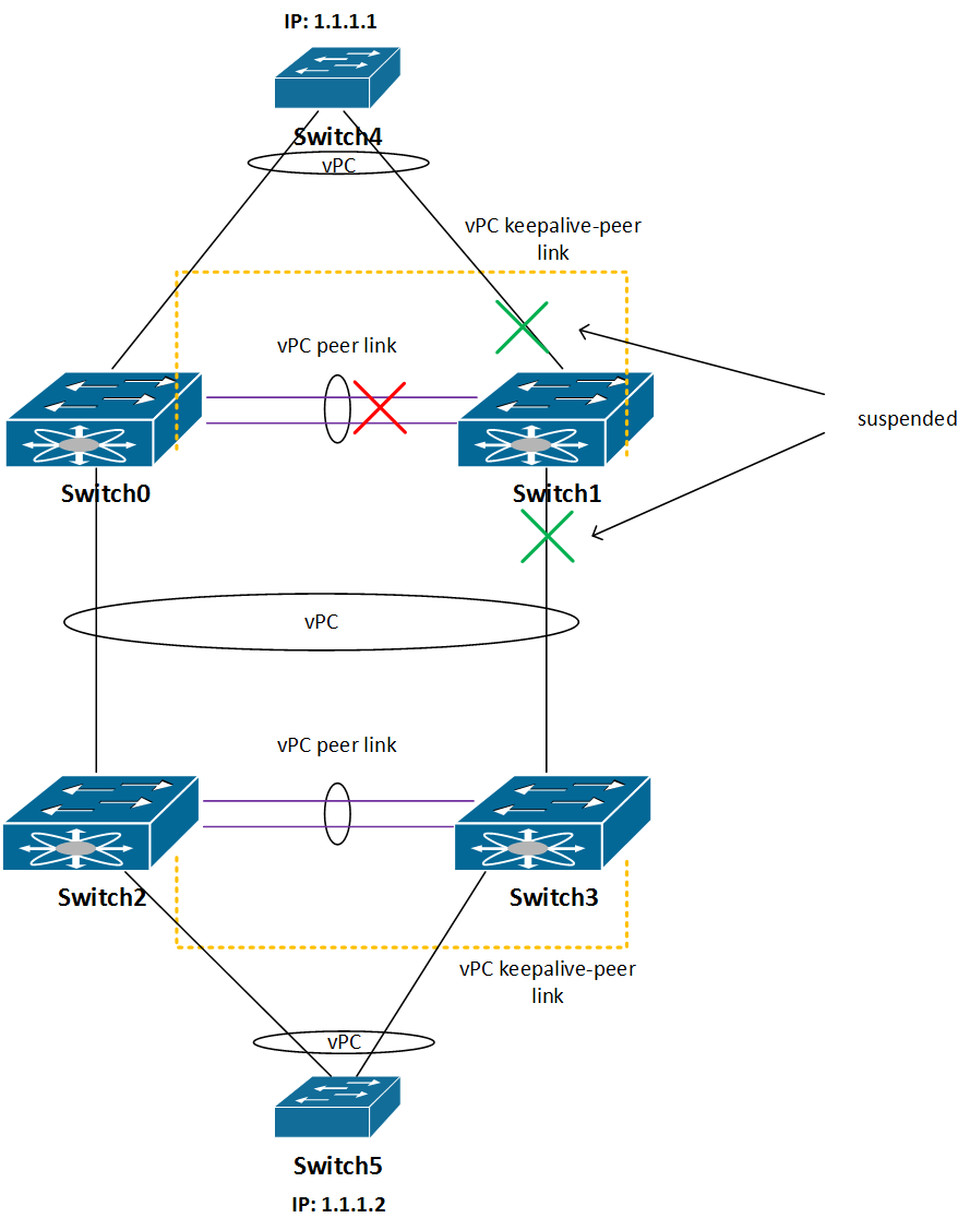
The connectivity between switches 4 and 5 is still OK, since the traffic goes through Switch0.
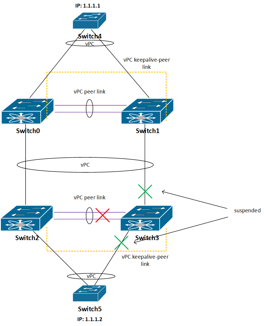
6. vPC peer link between Switch2 and Switch3 is disconnected, vPC keepalive link is OK
The same situation as in step 5.
7. both vPC keepalive and peer link between Switch0 and Switch1 are disconnected
This is even more interesting situation than previous one.
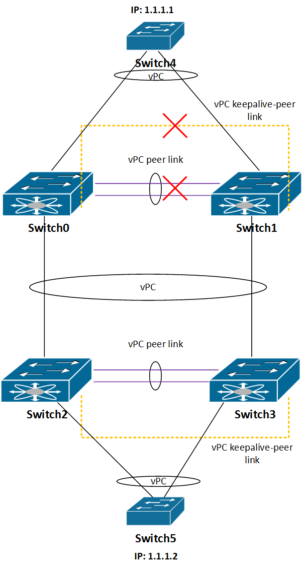
Because of the “auto-recovery” feature, we have now the situation that both Switch0 and Switch1 decided not to suspend their vPC ports. Although, the switches 4 and 5 will be able to re-establish connectivity, the short outage is inevitable.
8. both vPC keepalive and peer link between Switch2 and Switch3 are disconnected
Here’s the same situation as in step 7.
9. Shutting down uplinks on Switch4 and Switch5
This scenario case is the most harmless one in this series of redundancy tests, but I wanted it anyway.
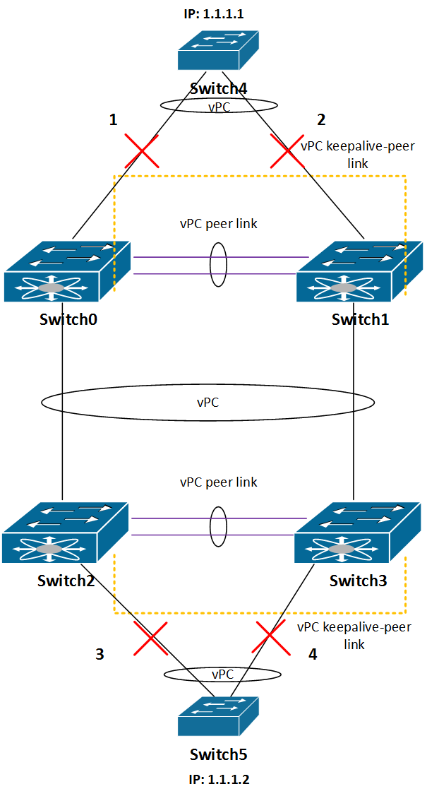
I was just doing “shut” “no shut” on port-channel member ports on each switch 4 and 5, the result was as expected – no connectivity loss.
Conclusion
vPC was behaving as expected, although in some situations above there were some connectivity issues when I was testing the redundancy with NX-OS version 5.0(3)U3(2a). As soon as I upgraded to 6.0(2)U2(2), the issues magically disappeared.
Even if there is not needed to pay any attention to STP in this setup, you should define some bridge priorities, just to keep things behaving as expected.
Nice one
Hello,
what is the VPC configuration performed between the 4 nexus 3K?
I need to configure an infrastructure with 2 nexus 5K and 2 Nexus 3K with the same architecture as yours.
Do I have to do one or two VPC between the 5K and 3K nexus?
Thanks you
Hi Arnaud G,
vPC configuration is shown on the page, and it will work between a pair of 5K and a pair of 3K. You can use only one vPC between two pairs, no need for more.
Simo
Hello Arnaud,
Is your setup worked with 2 nexus 5K and 2 Nexus 3 ?
Is this toplology exact? You only physically connected sw0 to sw2 ad sw1 to sw3?
@az1441,
That is correct.
Hello.
If you do that, I don’t understand how it can work because SW2 has no more physical path to Switch4.
While SW0 et SW3 are reloading they cannot forward any data.
Thanks in advance.
Hello Folio,
you are right. Second redundancy test was supposed to be done while Sw0 and Sw2 are reloading (not Sw0 and Sw3).
(2. Reload Switch0, Switch2 both at the same time).
Thanks for spotting this. I’ll make correction soon.
Hi Simo,
Can you share your config please? I am trying to archive the same in my setup (which is exactly the same topology) And it is not working… I have almost 40 second timeout till link become active again once i disconect any fiber between swiches. One diference in my configuration is that i am using vrf mgmt for keepalive link.. Any advices would be appreciated
Hi Szymon, unfortunately I don’t have config here since it has been more than 4 years when I had access to the equipment.