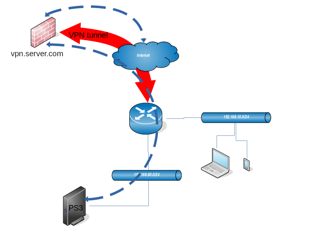
I will explain in this article how to set up routing on Mikrotik device in order to route traffic from certain network to VPN tunnel.
At home I have PS3 console with Netflix and I have access to different VPNs outside of country. Netflix catalogue differs from country to country, so the goal is to make Mikrotik to route all packets from/to PS3 to the VPN.
From the diagram above you can see that PS3 console is inside network 192.168.60.0/24. The goal is to route all the packets coming from this network (192.168.60.0/24) to the tunnel, and packets coming from the tunnel back to the clients in that network. Other clients in network 192.168.10.0/24 (laptop and smartphone) should be able to access internet directly without being router through the VPN.
VPN tunnel
In the example we are using simple PPTP type of VPN tunnel.
[admin@MikroTik] /interface pptp-client> print
Flags: X - disabled, R - running
 0  R name="pptp-vpn" max-mtu=1450 max-mru=1450 mrru=disabled connect-to=vpn.server.com user="test" password="test1234" profile=default-encryption keepalive-timeout=60 use-peer-dns=no add-default-route=no
      dial-on-demand=no allow=pap,chap,mschap1,mschap2
The name of pptp-client interface is “pptp-vpn”, we are connecting to “vpn.server.com” (host is here just for demo purpose). User, password and other arguments are left to defaults, but dns has to be “no” and add-default-route as well (we don’t want to route all local network through the tunnel).
When the VPN tunnel between Mikrotik router and VPN server (vpn.server.com) is established, a virtual “pptp-vpn” interface will be created. VPN server assigns to VPN client the IP 192.168.2.51:
[admin@MikroTik] > ip address print

Flags: X - disabled, I - invalid, D - dynamic

 #   ADDRESS            NETWORK         INTERFACE

 0   192.168.60.1/24    192.168.60.0    ether3

 1   192.168.10.1/30     192.168.10.0   ether2

 2 D 138.193.69.21/24   138.193.69.0    ether1

 3 D 192.168.2.50/32    192.168.2.1     pptp-vpn
Firewall settings
After we have successfully set up VPN tunnel connection with the server, we need to configure firewall on Mikrotik to route packets from client network 192.168.60.0/24 (where PS3 sits) to the VPN and vice-versa.
Address list
In order to easier keep a track which networks are used for what I like creating address list under firewall settings:
[admin@MikroTik] > ip firewall address-list print terse

 0   list=ps3 address=192.168.60.0/24 creation-time=jan/02/1970 01:47:58
Marking the packets
Everything what has source IP from network 192.168.60.0/24 will be marked with “vpn” string. It is configured in “ip firewall mangle” section:
[admin@MikroTik] > ip firewall mangle print

Flags: X - disabled, I - invalid, D - dynamic

 0    chain=prerouting action=mark-routing new-routing-mark=vpn passthrough=yes src-address-list=ps3 log=no log-prefix=""
To tell which packets with which source address to mark we use already configured “ps3” address-list.
Setting up the NAT for marked packets
In this scenario our box will be responsible for NAT where the packets from local network 192.168.60.0/24 will be behind dynamic IP address which we get assigned from PPTP (VPN) server.
[admin@MikroTik] > ip firewall nat print
Flags: X - disabled, I - invalid, D - dynamic
 0    chain=srcnat action=masquerade out-interface=ether1 log=no log-prefix=""

 1    chain=srcnat action=masquerade routing-mark=vpn src-address-list=ps3 log=no log-prefix=""
Entry under 0 is used to NAT non-marked (normal) traffic to reach internet, where entry 1 defines to NAT all packets with routing mark set to “vpn” and coming from src addresses in 192.168.60.0/24 network.
Routing setup
This is the last step, to route all packets with destination address 0.0.0.0/0 to VPN tunnel. Without this packet will be routed to default route (ether1) interface which we want to avoid.
[admin@MikroTik] > ip route print detail
Flags: X - disabled, A - active, D - dynamic, C - connect, S - static, r - rip, b - bgp, o - ospf, m - mme, B - blackhole, U - unreachable, P - prohibit
 0 A S  dst-address=0.0.0.0/0 gateway=192.168.2.1 gateway-status=192.168.2.1 reachable via  pptp-vpn distance=1 scope=30 target-scope=10 routing-mark=vpn
In this case we need to define gateway which is remote address of VPN interface – 192.168.2.1, routing-mark is “vpn” and dst-address “0.0.0.0/0”.
Checking the traffic
In order to see if everything has been set up correctly we can check each component in this setup:
- VPN tunnel
- Marking the packets
- NAT for marked packets
VPN tunnel check
Easiest way is to click on VPN interface in winbox and see if it is up and running and check the Traffic tab to see if there is actually some traffic showing up:
Marking the packets
If the packets from source network 192.168.60.0/24 are properly marked with “vpn” we can use tool in winbox under IP -> firewall -> Mangle
NAT for marked packets
To check if there is some NAT traffic for marked packets, we can use IP -> firewall -> NAT option in winbox.


